Language
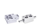
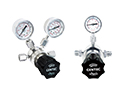
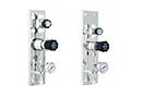
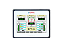
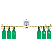
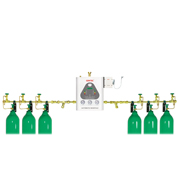
5200 Series Manual Single-Bank Manifold Systems
5200 series manual single-bank manifold system is designed for a single source of gas supply from one cylinder bank. 
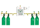
Although this system can be used as a main delivery system, it is typically used in industrial and medical applications as a high pressure emergency back-up system for liquid vessel or bulk systems.
Features
Open-style manifold
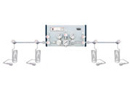
System can be designed for right or left bank
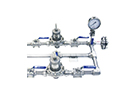
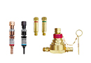
Silver brazing on piping joints for maximum leak prevention
System is designed to accomodate future expansion needs
System is mounted with gas filters
Pressure switch port is available
Headers have been tested to withstand high cylinder pressure
Wall or floor mount available
Installation Dimensions
Manifold System Layouts
Ordering Information
Gas Service Series Max. Inlet Pressure Delivery Pressure Max. Delivery Flow Outlet Connection Pigtail Specifications
Oxygen
5200X
3000 psi (207 bar)
50~200 psi (3.5~14 bar)
3500 SCFH (100 m3/h)
3/4" NPT (M)
Pigtail, CGA540
Acetylene
5200Y
435 psi (30 bar)
2~15 psi (0.14~1 bar)
700 SCFH (20 m3/h)
3/4" NPT (M)
Pigtail, CGA510
Propane
5200F
435 psi (30 bar)
15~125 psi (1~8.6 bar)
1050 SCFH (30 m3/h)
3/4" NPT (M)
Pigtail, CGA510
Carbon Dioxide
5200C
3000 psi (207 bar)
50~125 psi (3.5~8.6 bar)
2100 SCFH (60 m3/h)
3/4" NPT (M)
Pigtail, CGA320
Argon, Nitrogen, Helium
5200IN
3000 psi (207 bar)
50~125 psi (3.5~8.6 bar)
3500 SCFH (100 m3/h)
3/4" NPT (M)
Pigtail, CGA580
Air
5200Q
3000 psi (207 bar)
50~125 psi (3.5~8.6 bar)
3500 SCFH (100 m3/h)
3/4" NPT (M)
Pigtail, CGA346
Hydrogen
5200H
3000 psi (207 bar)
50~125 psi (3.5~8.6 bar)
10500 SCFH (300 m3/h)
3/4" NPT (M)
Pigtail, CGA350
EX: 52
Series
1
Manifold System Layout
2
Cylinder Valve Spacing
X
Gas Service
H
Max. Inlet Pressure
- 3
Number of Cylinders
R
Direction of Manifold Piping
- 1
Type of Mounting
54 1: Standard layout
2: “L” Shape layout
4: Crossover layout
5: Staggered layout
1: 5” (127 mm)
2: 10” (254 mm)
3: 13” (330 mm)
4: 18” (457 mm)
X: Oxygen
Y: Acetylene
F: Propane
C: Carbon Dioxide
IN: Ar, He, N2
Q: Air
H: Hydrogen
None: 2175 psi
H: 3000 psi
1: One cylinder
2: Two cylinders
3: Three cylinders
...
L: left
R: right
Note: Direction of
piping (Right or Left) is
indicated by facing the manifold.
1: Wall mount
2: Floor mount

Example: 5412X-5x5-1 indicates a 5 x 5 cylinder semi-automatic manifold system.

Distance between two cylinders is 10” on standard horizontal layout.


Download
2D
3D